|
|
||
|---|---|---|
| .. | ||
| Production | ||
| README.assets | ||
| Source | ||
| assets | ||
| .gitattributes | ||
| README.md | ||
| README_CN.md | ||
README.md
Marzipan

English | 简体中文
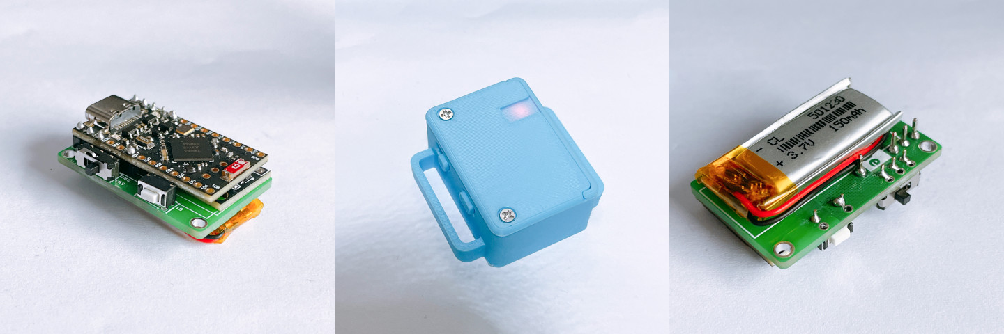
A compact and easy soldering modular Smol Slimes / nRFSlime solution with dimensions of 40x28x17mm!
If you'd like to learn more about Smol Slimes / nRFSlime, feel free to read the Smol Slime - SlimeVR Docs.
[!CAUTION] The current version (1.1) has the following issues:
- When using the ICM-45686 module from LWKJ, the sensor cannot be detected upon powering up the switch; you’ll need to press the button again to start it properly.
- The button's functionality does not behave as expected.
Pull Requests are welcome to help fix these issues!
Description
PCB
The PCB is designed using the EasyEDA Pro version, and the repository provides the source files for further modification.
For different pre-made sensor modules, I’ve created the following PCBs for different types. However, due to time constraints, only the VGGALXI version has been verified. The others should theoretically work.
VGGALXI: Pin order from bottom to top isVCC GND GND SDA SCL X INT(verified)VGLAXXI: Pin order from bottom to top isVCC GND SCL SDA X X INT(not verified)KOUNO'S_ICM45: Designed for KOUNO's module (not verified)
Case
For the case, two versions are provided:
Case_v5.stl, which requires M2 heat insert nuts.Case_v5_No_Heat_Insert_Nut.stl, where screws can be directly fastened into the case.
The version with heat insert nuts is more durable.
For Bambu Lab printers, pre-configured printing settings are provided here.
https://makerworld.com/zh/models/966982
The case files in the repository are designed to fit 25mm-wide straps and are also compatible with ReboCap’s quick-release system.
If you prefer wider straps, feel free to modify the .step source files.
Firmware
The pin positions of this PCB match the default layout in the original project (SDA-006, SCL-008, INT-017), so you can directly flash the firmware provided on the Smol Slime Docs without additional changes.
BOM
PCB and Assembly
The table below shows the components needed for one tracker. Note that you’ll also need to purchase one nRF52840 SuperMini/Dongle as a receiver. For more details, refer to the Smol Slime page.
According to the Discord community, one receiver can pair with approximately 20 trackers (this hasn’t been fully tested, but it should work for at least 6).
| Component | Qty | Notes |
|---|---|---|
| nRF52840 SuperMini Board | 1 | |
| MSK-12D19 Slide Switch | 1 | A legacy switch; other switches may also work |
| 364.3 Tactile Switch (Side) | 1 | Other side tactile switches can also be used |
| 401230 / 501230 Battery | 1 | 501230 is recommended; smaller batteries are also fine |
| Double-sided tape for battery | 1 | |
| Sensor Module | 1 | |
| M2*14 Screws | 2 | Used to secure the case |
| M24.53 Heat Insert Nut | 2 | Not needed for the screw-only case version |
| 25mm-wide strap | 1 | You can modify the case files for other straps |
3D Printing
For 3D printing, PETG is recommended, but PLA is also fine.
| Component | Qty | Notes |
|---|---|---|
| Lid_v5 | 1 | The lid |
| Case_v5 | 1 | Case body that requires heat insert nuts; use Case_v5_No_Heat_Insert_Nut if not needed |
| Button_Cap_v5 | 1 | Button cap for extending buttons |
| Switch_Cap_v5 | 1 | Switch cap for extending switches |
| Screw_Holder_v5 | 2 | Screw support pillars; optional but increases durability |
Assembly Instructions
Soldering and Assembly
-
(Optional) Use a probe or other tools to check if the SuperMini, sensor module, etc., are functioning properly.
-
Solder the sensor module first:
- Make sure the sensor’s pin order matches the PCB.
- Align the pins and secure them by melting solder from the back of the PCB. After soldering, use a multimeter to ensure the circuit is properly connected.
-
Solder the switch and button.
-
Make sure the switch is in the OFF position, then solder the battery.
-
Finally, solder the SuperMini module.
-
After confirming normal functionality, stick the battery to the back of the PCB using double-sided tape in the designated rectangular area.
-
Embed the heat insert nut into the Case.
-
Install the button and switch caps into the case, align the holes, and insert the main body into the case.
-
Insert the screw support pillars, attach the lid, and fasten the screws.
Flashing Firmware
- Refer to the Smol Slime Docs for instructions on flashing firmware.
- When using LWKJ's ICM-45686 module +
VGGALXIlayout, the firmware configurationTracker SuperMini Disabled Disabledworks properly.
- When using LWKJ's ICM-45686 module +
Links
-
SlimeVR nRF Receiver Firmware: https://github.com/SlimeVR/SlimeVR-Tracker-nRF-Receiver
-
SlimeVR nRF Tracker Firmware: https://github.com/SlimeVR/SlimeVR-Tracker-nRF
-
Scawanf's PCB R3 on Github: https://github.com/SlimeVR/SlimeVR-Tracker-nRF-PCB
-
Scawanf's PCB R3 on OSHWLab: https://oshwlab.com/sctanf/slimenrf3
-
SlimeVR Discord: https://discord.gg/SlimeVR
-
Smol Slime Docs: https://docs.slimevr.dev/diy/smol-slime.html